You can move faces by assigning dimensions between edges.
It is one of my popular commands, but in the new versions, it is currently hidden. Most of the users don’t know this useful synchronous modeling command. You can find this command by typing “Linear Dimension” in the command finder.
For starting command:
- Select the command from “Menu => Insert => Synchronous modeling => Dimension => Linear Dimension”
- Click the drop-down arrow near Synchronous modeling group => More Gallery => Activate “Relate Gallery” (Also you can activate or deactivate other commands in the list) Relate Gallery commands will open in the “More” in the “Synchronous Modeling” group. (Shown in the figure)


For using command
- Activate the “Linear Dimension” command in the Synchronous modeling group. (First, add command in the group)
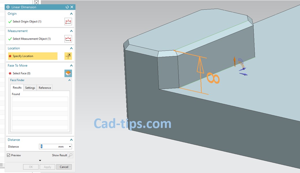
- Select the stationary edge on the model. (“Select Origin Object” will be highlighted when the command window opened. Always look at the command window to see which tab highlighted.)
- “Select Measurement Object” will be highlighted automatically. Select edge on the face to move.
- The dimension will occur on the screen and the “Specify Location” will be highlighted on the command window. Click on the screen where you want to place the dimension if the direction of the dimension is true. (If you want to change dimension direction, open more options in the command window and change the direction from the “Orientation” tab)
- Select other faces to move. (Don’t forget only selected faces will move)
- Type new dimension value in the “Distance” box or drag the arrowhead on the screen.
- Click the middle mouse button twice or “Ok” to finish command. To finish and activate the same command, click “Apply” in the command window.