Your Privacy Choices Skip to content

cad-tips

cad tips and tutorials

  • HOME
  • NX 11 TUTORIAL
  • NX 1867 TUTORIAL
  • NX 2206 TUTORIAL
  • About

Make Corner

Posted on January 26, 2020 by admin Leave a Comment on Make Corner

You can make corners between curves in the sketch of the NX. If both curves intersect, the curves are trim to make a corner. If the curves do not intersect, both curves extend to create a corner between the curves.

To create a corner

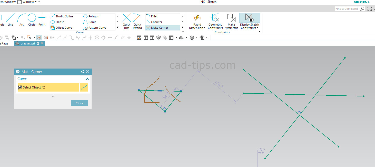
  1. Start the “Make Corner” command.
  2. Select the inner side of the curves. (You can select by dragging the mouse cursor)
  3. The corners on the curves will create on the graphics window.
  4. Press the “Esc” on the keyboard or press the middle mouse button.
Posted in Siemens NX Tagged Curve Group, NX lecture notes, NX tutorial, sketch

Post navigation

Polygon →
← Simple Part Modeling-1

Author: admin

Leave a Reply Cancel reply

Your email address will not be published. Required fields are marked *


Search

  • Starting NX Continuous Release
    • Creating a New File
    • Opening File
    • The Mouse Functions in Siemens NX
      • The Left Mouse Button functions in NX
      • The Right Mouse Button functions in NX
      • The Middle Mouse Button in Siemens NX
    • Zoom
    • Rotate
    • Pan
    • Change color in Modeling
    • Edit Background
    • Close Part Files
    • Roles in the NX
    • Full Screen working in NX
    • Selection Scope
  • Sketch
    • Creating Sketch on a Curve/Edge in NX
    • Profile
    • Line
    • Rectangle
    • Circle
    • Arc
    • Polygon
    • Point
    • Rapid Dimension
    • Mirror Curve
    • Quick Trim
    • Quick Extend
    • Make Corner
    • Creating Projected Curve in NX Sketch
    • Offset Curve in NX Sketch
    • Pattern Curve
      • Linear Pattern
      • Circular Pattern
      • General Pattern
    • 2D Synchronous Commands in NX Sketch
      • Move Curve in NX Sketch
      • Offset Move Curve in NX Sketch
      • Resize Curve in NX Sketch
      • Resize Chamfer Curve in NX Sketch
      • Scale Curve in NX Sketch
      • Delete Curve in NX Sketch
    • Snap Settings
    • Constraints on Sketch
      • Show or Hide Constraints in the Sketch
  • Extrude
    • The Section in Extrude
    • The Direction in Extrude
    • Limits in Extrude
    • Boolean Operations in Extrude in NX 12
    • Offset in Extrude
  • Revolve
  • Detail Feature
    • Edge Blend
    • Chamfer
    • Draft
    • Shell
  • Text
    • Advance Text in NX Modeling
  • Changing Object Color in NX
  • Scale Body in NX
  • Creating Solid Wall on Sheet Surface in NX
  • Move Object in NX
  • Associative Copy
    • Pattern Feature
      • Linear Pattern Feature
      • Circular Pattern
    • Mirror Feature
    • Mirror Geometry
    • WAVE Geometry Linker
    • Extract Geometry
  • Sheet Metal
    • Tab
    • Contour Flange
    • Flange
    • Bend
    • Jog
    • Normal Cutout
    • Closed Corner
    • Unbend
    • Rebend
    • Convert to Sheet Metal
  • Synchronous Modeling
    • Move Face
      • Example: Move Face
    • Offset Region
    • Delete Face
    • Replace Face
    • Pull Face
    • Resize Face
    • Resize Blend
    • Resize Chamfer
    • Relate Gallery
      • Linear Dimension
      • Radial Dimension
      • Angular Dimension
      • Make Perpendicular
      • Make Parallel
      • Make Coaxial
      • Make Tangent
      • Edit Cross Section
  • Assembly Modeling
    • Starting Assembly
    • Add Component
    • Creating Part in Assembly
    • Creating New Part Component from the body in NX
    • Create New Parent
    • Changing the Component Name in the Assembly in NX
    • Move Component
    • Mirror Assembly in NX
    • Pattern Component in NX
      • Linear Pattern of Components
      • Circular Pattern of Components
      • Pattern Components Through Reference Objects
      • General Pattern in Assembly Modeling
    • Assembly Constraints
      • Touch Align two Parts in Assembly
      • Distance Constraint
      • Concentric constraints in Assembly
      • Fix Part Position in the Assembly
      • Parallel constraints in the Assembly
      • Perpendicular constraints in the Assembly
      • Align/Lock
      • Bond
      • Center constraint in Assembly
      • Angle Constraint
    • Make Unique
    • Suppress Component
    • Open in New Window
    • Show Degrees of Freedom
    • Changing Part Color in Assembly
    • Create Associative Curve in Assembly Sketch
  • Datums
    • Datum Plane
    • Datum Axis
    • Datum CSYS
  • Importing Image in the 3D model in NX
  • Measure
    • Measure Distance
      • Projected Distance
    • Measure Radius/Diameter
    • Measure Angle
    • Measure Curve/Edge length
    • Measure Face
    • Measure Body
    • Measure Problems in NX
  • Drafting
    • New Sheet
    • View Creation Wizard
    • Base View
      • Sheet Metal Flatten Pattern View in Drafting
      • Orient View Tool
    • Section View
    • Projected View
    • Hide Smooth Edges in the Drafting
    • Detail View
    • Dimension
      • Rapid Dimension
      • Linear Dimension
      • Radial Dimension
      • Angular Dimension
      • Chamfer
      • Tangent Dimensioning to Circular Edge in Drafting
    • Note
    • Area Fill
    • Datum Feature Symbol
    • Changing Projection Angle in NX Drafting
    • QuickPick
Copyright © 2025 cad-tips | Design by ThemesDNA.com